



Equipos para Calefacción y ACS
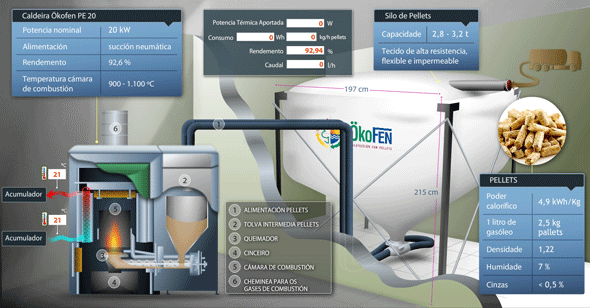
La caldera de biomasa está emplazada en la sala de instalaciones térmicas de la vivienda bioclimática demostrativa, ubicada en el Parque Eólico Experimental Sotavento. El equipo utiliza pellets cómo biocombustible, los cuales son cargados mediante transporte neumático desde un silo con capacidad para 2.500 kg. situado en el almacén de la vivienda. La potencia térmica nominal del equipo es de 20 kW.

El aporte de energía de la caldera al sistema de calefacción y ACS se efectúa a través de un depósito de inercia estratificado de 800 litros. Sobre este depósito, además de la caldera de biomasa, se conecta una bomba de calor geotérmica capaz de aportar energía de modo paralelo, operando sobre la parte superior e inferior del acumulador respectivamente. Desde este depósito se impulsa y retorna el agua caliente destinada a la calefacción por suelo radiante. Además, incorpora un intercambiador interno del tipo serpentín destinado a la producción de ACS.
Parámetros monitorizados
Los parámetros almacenados y monitorizados para este equipo son:
- Temperatura de fluido en la entrada y salida de la caldera
- Temperaturas del depósito de inercia en cinco niveles
- Caudal circulante
- Potencia instantánea transmitida
- Energía térmica transmitida
Características técnicas
| Marca y Modelo | OKPFEN PELLEMATIC PE20 |
|---|---|
| Potencia calorífica nominal | 20 kW |
| Ancho total | 1.130 mm |
| Ancho de la caldera | 700 mm |
| Altura de la caldera | 1.090 mm |
| Fondo-caldera | 814 mm |
| Diámetro conexiones ida/retorno | 1″ |
| Diámetro chimenea de humo | 150 mm |
| Peso | 250 kg |
| Conexión eléctrica | 230 V 50 Hz |
| Rendimiento | 92,6% |
| Rendimiento con carga parcial | 91,1% |
| Contenido en agua | 66 L |
| Temperaturas gases de combustión | 160 ºC |
Aplicación demostrativa
Sotavento dispone de una aplicación demostrativa, visual e interactiva, que permite ver los datos de la instalación en tiempo real y realizar múltiples cálculos y extrapolaciones.
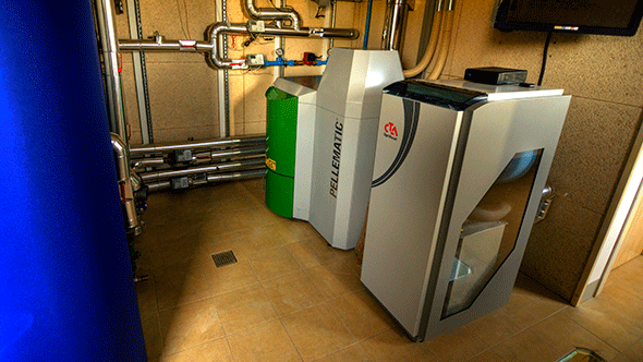
La bomba de calor geotérmica, al igual que la caldera de biomasa, está emplazada en la sala de instalaciones térmicas de la vivienda bioclimática ubicada en el Parque Eólico Experimental Sotavento. El equipo posee su circuito frigorífico, en el lado del evaporador, conectado a un intercambiador geotérmico horizontal. Básicamente este intercambiador consiste en 500 m. de tubería de polietileno de DN 32 mm. ubicada bajo material de relleno procedente de la excavación de la propia vivienda, a una profundidad media de 2 m., y que permite la extracción de energía térmica del terreno para emplearla en cubrir las demandas de la vivienda. La bomba de calor dispone de una potencia calorífica nominal de 8,2 KW y un COP de 4,7 (COP para una temperatura media en el evaporador 0ºC y de 35ºC en el condensador, excluyendo el consumo eléctrico de las bombas circuladoras). La bomba de calor trabaja bajo demanda sobre la parte inferior de un depósito de inercia estratificado de 800 litros.
Parámetros monitorizados
Los parámetros almacenados y monitorizados para este equipo son:
- Temperatura del fluido a la entrada y salida de la bomba de calor, circuito geotérmico
- Temperatura del fluido a la entrada y salida de la bomba de calor, circuito secundario
- Temperaturas del depósito de inercia en cinco niveles
- Caudal circulante en el circuito secundario
- Potencia instantánea transmitida
- Energía térmica transmitida
- Temperatura del terreno en el intercambiador geotérmico en 32 puntos
- Temperatura de referencia del terreno no perturbado
Características técnicas
| Marca y Modelo | OPTIHEAT 8es |
|---|---|
| Potencia calorífica nominal1 | 8,2 kW |
| COP1 | 4,7 |
| Potencia eléctrica nominal absorbida | 1,7 kW |
| Caudal de agua en el evaporador (ΔT=3ºC) | 2,00 m3/h |
| Caudal de agua en el condensador (ΔT=10ºC) | 0,71 m3/h |
| Ancho de la bomba | 1.260 mm |
| Altura de la bomba | 700 mm |
| Fondo de la bomba | 530 mm |
| Tipo de refrigerante/carga | 410A/2,1 kg |
| Max. potencia eléctrica absorbida | 5,4 kW |
| Max. potencia eléctrica absorbida incluyendo bombas | 5,9 kW |
| Conexión eléctrica | 400-3 V 50 Hz |
1 Sin incluir el consumo eléctrico de las bombas circuladoras, y para temperatura media del evaporador de 0ºC y de 35ºC en el condensador.
Aplicación demostrativa
Sotavento dispone de una aplicación demostrativa, visual e interactiva, que permite ver los datos de la instalación en tiempo real y realizar múltiples cálculos y extrapolaciones.

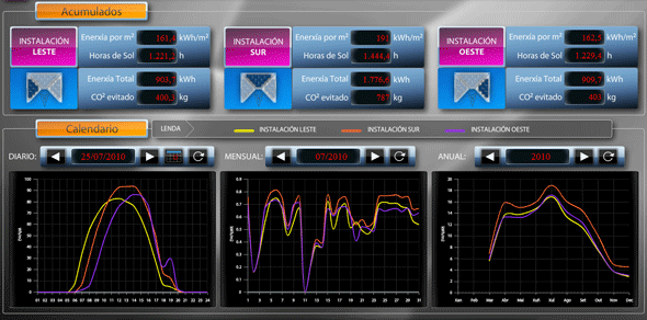
Los datos de estos circuitos son monitorizados de modo independiente con la finalidad de poder efectuar análisis comparativos. La instalación la conforman un total de 22 módulos fotovoltaicos de silicio policristalino con una potencia individual de 123 Wp (Vatios pico), lo que supone una potencia total instalada de 2.706 Wp.
Los equipos se distribuyen del siguiente modo según la orientación:
| Instalación | Orientación | Nº Paneles | Wp | Inversor |
|---|---|---|---|---|
| Este | 90º | 6 | 738 | Mastervolt Soladin 600 |
| Sur | 180º | 10 | 1.230 | Sunnyboy 1100 |
| Oeste | 270º | 6 | 738 | Mastervolt Soladin 600 |
Parámetros monitorizados
- Potencia instantánea de cada subsistema fotovoltaico (Este, Sur y Oeste)
- Energía generada acumulada por cada subsistema fotovoltaico (Este, Sur y Oeste)
- Tensión, intensidad y potencia en el lado de continua de cada subsistema
- Tensión, intensidad, potencia activa y reactiva en el lado de alterna de cada subsistema
- Radiación y temperatura de cada subsistema
- Humedad y velocidad del viento
Características de los módulos
| Marca y Modelo | Photowatt PW6-123 |
|---|---|
| Potencia nominal | 123 W |
| Tensión en circuito abierto | 21,9 V |
| Tensión Mpp | 17,6 V |
| Intensidad en cortocircuito | 7 A |
| Intensidad Mpp | 7,6 A |
Características del Inversor
| Marca y Modelo | SMA Sunnyboy 1100 | Mastervolt Soladin 600 |
|---|---|---|
| ENTRADA CC | ||
| Potencia máxima de CC | 1.210 W | 600 W |
| Tensión máx. de CC | 400 V | 155 V |
| Corriente max. de entrada | 10 A | 4 A |
| SALIDA CA | ||
| Potencia nominal | 1.000 W | 525 W |
| Potencia máxima | 1.100 W | 725 W |
| Tensión CA salida | 220/240 V – 50 Hz | 195/253 V – 50 Hz |
| Corriente max. salida | 5,6 A | 2,25 A |
| Conexión de CA | Monofásica | Monofásica |
| Rendimiento | 91,6 % | 91,0 % |
Aplicación demostrativa
Sotavento dispone de una aplicación demostrativa, visual e interactiva, que permite ver los datos de la instalación en tiempo real y realizar múltiples cálculos y extrapolaciones.
- Caldera de Biomasa
-
La caldera de biomasa está emplazada en la sala de instalaciones térmicas de la vivienda bioclimática demostrativa, ubicada en el Parque Eólico Experimental Sotavento. El equipo utiliza pellets cómo biocombustible, los cuales son cargados mediante transporte neumático desde un silo con capacidad para 2.500 kg. situado en el almacén de la vivienda. La potencia térmica nominal del equipo es de 20 kW.
El aporte de energía de la caldera al sistema de calefacción y ACS se efectúa a través de un depósito de inercia estratificado de 800 litros. Sobre este depósito, además de la caldera de biomasa, se conecta una bomba de calor geotérmica capaz de aportar energía de modo paralelo, operando sobre la parte superior e inferior del acumulador respectivamente. Desde este depósito se impulsa y retorna el agua caliente destinada a la calefacción por suelo radiante. Además, incorpora un intercambiador interno del tipo serpentín destinado a la producción de ACS.
Parámetros monitorizados
Los parámetros almacenados y monitorizados para este equipo son:
- Temperatura de fluido en la entrada y salida de la caldera
- Temperaturas del depósito de inercia en cinco niveles
- Caudal circulante
- Potencia instantánea transmitida
- Energía térmica transmitida
Características técnicas
Marca y Modelo OKPFEN PELLEMATIC PE20 Potencia calorífica nominal 20 kW Ancho total 1.130 mm Ancho de la caldera 700 mm Altura de la caldera 1.090 mm Fondo-caldera 814 mm Diámetro conexiones ida/retorno 1″ Diámetro chimenea de humo 150 mm Peso 250 kg Conexión eléctrica 230 V 50 Hz Rendimiento 92,6% Rendimiento con carga parcial 91,1% Contenido en agua 66 L Temperaturas gases de combustión 160 ºC Aplicación demostrativa
Sotavento dispone de una aplicación demostrativa, visual e interactiva, que permite ver los datos de la instalación en tiempo real y realizar múltiples cálculos y extrapolaciones.
- Bomba de Calor Geotérmica
-
La bomba de calor geotérmica, al igual que la caldera de biomasa, está emplazada en la sala de instalaciones térmicas de la vivienda bioclimática ubicada en el Parque Eólico Experimental Sotavento. El equipo posee su circuito frigorífico, en el lado del evaporador, conectado a un intercambiador geotérmico horizontal. Básicamente este intercambiador consiste en 500 m. de tubería de polietileno de DN 32 mm. ubicada bajo material de relleno procedente de la excavación de la propia vivienda, a una profundidad media de 2 m., y que permite la extracción de energía térmica del terreno para emplearla en cubrir las demandas de la vivienda. La bomba de calor dispone de una potencia calorífica nominal de 8,2 KW y un COP de 4,7 (COP para una temperatura media en el evaporador 0ºC y de 35ºC en el condensador, excluyendo el consumo eléctrico de las bombas circuladoras). La bomba de calor trabaja bajo demanda sobre la parte inferior de un depósito de inercia estratificado de 800 litros.
Parámetros monitorizados
Los parámetros almacenados y monitorizados para este equipo son:
- Temperatura del fluido a la entrada y salida de la bomba de calor, circuito geotérmico
- Temperatura del fluido a la entrada y salida de la bomba de calor, circuito secundario
- Temperaturas del depósito de inercia en cinco niveles
- Caudal circulante en el circuito secundario
- Potencia instantánea transmitida
- Energía térmica transmitida
- Temperatura del terreno en el intercambiador geotérmico en 32 puntos
- Temperatura de referencia del terreno no perturbado
Características técnicas
Marca y Modelo OPTIHEAT 8es Potencia calorífica nominal1 8,2 kW COP1 4,7 Potencia eléctrica nominal absorbida 1,7 kW Caudal de agua en el evaporador (ΔT=3ºC) 2,00 m3/h Caudal de agua en el condensador (ΔT=10ºC) 0,71 m3/h Ancho de la bomba 1.260 mm Altura de la bomba 700 mm Fondo de la bomba 530 mm Tipo de refrigerante/carga 410A/2,1 kg Max. potencia eléctrica absorbida 5,4 kW Max. potencia eléctrica absorbida incluyendo bombas 5,9 kW Conexión eléctrica 400-3 V 50 Hz 1 Sin incluir el consumo eléctrico de las bombas circuladoras, y para temperatura media del evaporador de 0ºC y de 35ºC en el condensador.
Aplicación demostrativa
Sotavento dispone de una aplicación demostrativa, visual e interactiva, que permite ver los datos de la instalación en tiempo real y realizar múltiples cálculos y extrapolaciones.
Los datos de estos circuitos son monitorizados de modo independiente con la finalidad de poder efectuar análisis comparativos. La instalación la conforman un total de 22 módulos fotovoltaicos de silicio policristalino con una potencia individual de 123 Wp (Vatios pico), lo que supone una potencia total instalada de 2.706 Wp.
Los equipos se distribuyen del siguiente modo según la orientación:Instalación Orientación Nº Paneles Wp Inversor Este 90º 6 738 Mastervolt Soladin 600 Sur 180º 10 1.230 Sunnyboy 1100 Oeste 270º 6 738 Mastervolt Soladin 600 Parámetros monitorizados
- Potencia instantánea de cada subsistema fotovoltaico (Este, Sur y Oeste)
- Energía generada acumulada por cada subsistema fotovoltaico (Este, Sur y Oeste)
- Tensión, intensidad y potencia en el lado de continua de cada subsistema
- Tensión, intensidad, potencia activa y reactiva en el lado de alterna de cada subsistema
- Radiación y temperatura de cada subsistema
- Humedad y velocidad del viento
Características de los módulos
Marca y Modelo Photowatt PW6-123 Potencia nominal 123 W Tensión en circuito abierto 21,9 V Tensión Mpp 17,6 V Intensidad en cortocircuito 7 A Intensidad Mpp 7,6 A Características del Inversor
Marca y Modelo SMA Sunnyboy 1100 Mastervolt Soladin 600 ENTRADA CC Potencia máxima de CC 1.210 W 600 W Tensión máx. de CC 400 V 155 V Corriente max. de entrada 10 A 4 A SALIDA CA Potencia nominal 1.000 W 525 W Potencia máxima 1.100 W 725 W Tensión CA salida 220/240 V – 50 Hz 195/253 V – 50 Hz Corriente max. salida 5,6 A 2,25 A Conexión de CA Monofásica Monofásica Rendimiento 91,6 % 91,0 % Aplicación demostrativa
Sotavento dispone de una aplicación demostrativa, visual e interactiva, que permite ver los datos de la instalación en tiempo real y realizar múltiples cálculos y extrapolaciones.
ACCESO Y DESCARGA DE DATOS
Los parámetros de las instalaciones eólicas del Parque Eólico Sotavento son almacenados en una base de datos e integrados en una aplicación de descarga. Esta aplicación, permite a las organizaciones, empresas o universidades con las que sotavento mantiene convenios de colaboración el acceso a los datos de necesarios para el desarrollo de proyectos.
Listado completo de los parámetros almacenados en las instalaciones del parque eólico y vivienda bioclimática
